
NCERT Solutions for Class 7 Science Chapter – 3 Electricity Circuits and their components Questions and Answers New NCERT Updated Syllabus
Let Us Enhance Our Learning page no: 37-39
Question 1. Choose the incorrect statement.
(i) A switch is the source of electric current in a circuit.
(ii) A switch helps to complete or break the circuit.
(iii) A switch helps us to use electricity as per our requirement.
(iv) When the switch is in ‘OFF’ position, there is an air gap between its terminals.
Answer: The incorrect statement is (i): “A switch is the source of electric current in a circuit.”
To analyze the statements regarding switches in an electrical circuit, let’s evaluate each one:
- (i) A switch is the source of electric current in a circuit.
- Incorrect: A switch does not generate electric current; it merely controls the flow of current by opening or closing the circuit.
- (ii) A switch helps to complete or break the circuit.
- Correct: This is true. A switch can either complete the circuit (allowing current to flow) or break the circuit (stopping the flow of current).
- (iii) A switch helps us to use electricity as per our requirement.
- Correct: This statement is accurate as switches allow users to turn devices on or off based on their needs.
- (iv) When the switch is in ‘OFF’ position, there is an air gap between its terminals.
- Correct: This is also true. In the ‘OFF’ position, the switch creates an open circuit, resulting in an air gap that prevents current from flowing.
Question 2. Observe Fig. 3.16. With which material connected between the ends A and B, the lamp will not glow?
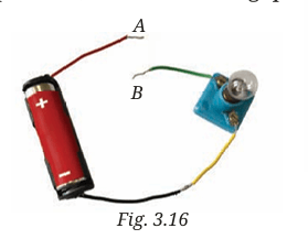
Answer: To determine which material will not allow the lamp to glow when connected between the ends A and B, we need to consider the properties of electrical conductors and insulators. Materials that are good conductors of electricity, such as metals (like copper or aluminum), will allow the current to flow and the lamp to glow. Conversely, materials that are insulators, such as rubber, plastic, wood, or glass, will not conduct electricity and therefore will prevent the lamp from glowing.
For example, if you connect a rubber band or a piece of plastic between the ends A and B, the lamp will not glow because these materials do not allow electric current to pass through them.
Key Point: Insulating materials do not conduct electricity and will cause the circuit to remain open, preventing the lamp from lighting up.
Question 3. In Fig. 3.17, if the fi lament of one of the lamps is broken, will the other glow? Justify your answer
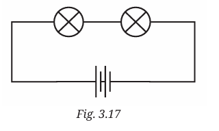
Answer: In a circuit where two lamps are connected in series, if the filament of one lamp breaks, the other lamp will not glow. This is because a series circuit requires a complete path for electric current to flow. When one lamp’s filament is broken, it creates an open circuit, interrupting the flow of current. As a result, the electric current cannot reach the second lamp, preventing it from glowing.
Conversely, if the lamps were connected in parallel, the failure of one lamp would not affect the operation of the other, as each lamp would have its own independent path for current flow. Thus, in the case of series connections, the integrity of each component is crucial for the entire circuit’s functionality.
Key Point: In a series circuit, the failure of one component disrupts the entire circuit, while in a parallel circuit, other components can still function independently.
Question 4. A student forgot to remove the insulator covering from the connecting wires while making a circuit. If the lamp and the cell are working properly, will the lamp glow?
Answer: If the student did not remove the insulator covering from the connecting wires while making the circuit, the lamp will not glow, even if both the lamp and the cell are functioning properly. This is because the insulating material, typically made of rubber or plastic, prevents the flow of electric current.
For an electric circuit to work, there must be a complete path for the current to travel from the power source (the cell) through the wires to the lamp and back. Insulators block the flow of electricity, creating an open circuit. Therefore, without direct contact between the conductive parts of the wires, the circuit remains incomplete, and the lamp will not receive any current to illuminate.
Key Point: Insulation on wires is crucial for safety, but it must be removed at the connection points to allow current to flow and power the circuit.
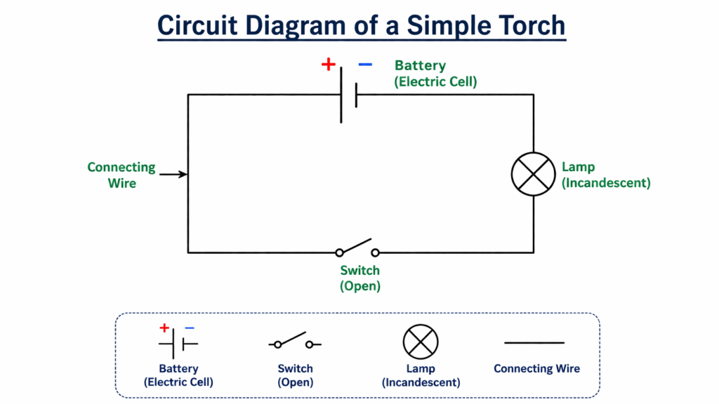
Question5. Draw a circuit diagram for a simple torch using symbols for electric components.
Answer: To create a circuit diagram for a simple torch, we will use standard symbols to represent the components involved. The circuit typically includes the following elements:
1. Battery (or Electric Cell): Represented by a long line (positive terminal) and a short line (negative terminal).
2. Switch: Represented by a break in the line that can be closed or opened.
3. Lamp (Incandescent or LED): Represented by a circle with a cross inside for an incandescent lamp or a triangle pointing towards a line for an LED.
4. Connecting Wires: Represented by straight lines connecting the components.
Description:
– The battery provides the electrical energy needed for the circuit.
– The switch controls the flow of electricity, allowing the user to turn the torch on or off.
– The lamp is where the light is produced when the circuit is complete.
– Connecting wires link all components, forming a closed loop for current to flow.
📌 Key Point: A circuit diagram simplifies the representation of electrical circuits, making it easier to understand the connections and functionality of each component.
Question 6. In Fig. 3.18:
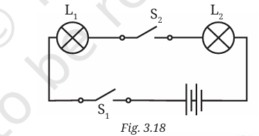
(i) If S2 is in ‘ON’ position, S1 is in ‘OFF’ position, which lamp(s) will glow?
Answer: If switch S2 is in the ‘ON’ position and switch S1 is in the ‘OFF’ position, only the lamp connected to S2 will glow. This is because the circuit path through S1 is open, preventing current from flowing to the lamp connected to S1. The closed circuit through S2 allows current to flow, illuminating the lamp associated with it.
(ii) If S2 is in ‘OFF’ position, S1 is in ‘ON’ position, which lamp(s) will glow?
Answer: If switch S2 is in the ‘OFF’ position and switch S1 is in the ‘ON’ position, only the lamp connected to S1 will glow. In this scenario, the circuit path through S2 is open, stopping current from reaching the lamp connected to S2. However, since S1 is closed, current can flow through the lamp connected to S1, causing it to light up.
(iii) If S1 and S2 both are in ‘ON’ position, which lamp(s) will glow?
Answer: If both switches S1 and S2 are in the ‘ON’ position, both lamps will glow. With both switches closed, the circuit paths for both lamps are complete, allowing current to flow through each lamp. As a result, both lamps will illuminate simultaneously.
(iv) If both S1 and S2 are in ‘OFF’ position, which lamp(s) will glow?
Answer: If both switches S1 and S2 are in the ‘OFF’ position, neither lamp will glow. In this case, both circuit paths are open, preventing any current from flowing through the lamps. Therefore, without a complete circuit, the lamps will not receive power and will remain off.
Key Point: The operation of lamps in a circuit depends on the positions of the switches controlling the flow of current. Each switch can independently affect whether its corresponding lamp glows or not.
Question 7. Vidyut has made the circuit as shown in Fig. 3.19. Even after closing the circuit, the lamp does not glow. What can be the possible reasons? List as many possible reasons as you can for this faulty operation. What will you do to find out why the lamp did not glow?
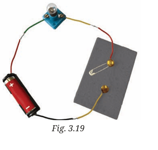
Answer: If the lamp in Vidyut’s circuit does not glow even after closing the circuit, several potential reasons could be causing this issue:
1. Broken Filament: The filament inside the lamp may be broken, preventing current from flowing through it. This is a common issue with incandescent lamps.
2. Faulty Connections: There might be loose or faulty connections between the wires, lamp, and battery. Any gap in the circuit can interrupt the flow of electricity.
3. Dead Battery: The battery may be depleted or not functioning properly, which means it cannot provide the necessary voltage to power the lamp.
4. Incorrect Wiring: The components may not be connected in the correct order or configuration, leading to an incomplete circuit.
5. Insulation Issues: If the wires are not properly stripped of insulation at the connection points, the current may not be able to flow through the circuit.
6. Short Circuit: There could be a short circuit occurring if the wires are touching each other inappropriately, bypassing the lamp altogether.
Steps to Diagnose the Issue:
To find out why the lamp did not glow, the following steps can be taken
1. Check the Lamp: Inspect the lamp for any visible signs of damage or a broken filament. If possible, replace it with a known working lamp to see if that resolves the issue.
2. Test the Battery: Use a multimeter to measure the voltage of the battery. If the voltage is low or zero, replace the battery with a fresh one.
3. Examine Connections: Carefully inspect all connections in the circuit. Ensure that all wires are securely connected and that there are no loose ends.
4. Verify Wiring Configuration: Double-check the wiring configuration against a circuit diagram to ensure all components are connected correctly.
5. Inspect Wires: Look for any insulation that may not have been removed from the ends of the wires. Ensure that the metal parts are exposed and making contact.
6. Test for Short Circuits: Ensure that no wires are touching each other inappropriately. This can be done by visually inspecting the circuit and adjusting the wires as necessary.
By systematically checking each of these potential issues, Vidyut can identify the cause of the problem and take corrective action to ensure the lamp glows when the circuit is closed.
Key Point: Troubleshooting electrical circuits involves checking each component systematically to identify and resolve issues that prevent current flow.
Question 8. In Fig. 3.20, in which case(s) the lamp/LED will not glow when the switch is closed?
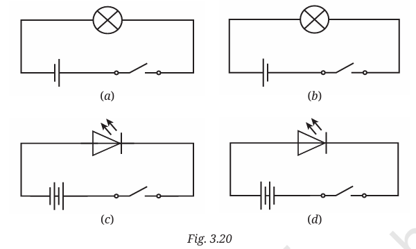
Answer: To determine in which cases the lamp or LED will not glow when the switch is closed in Fig. 3.20, we need to consider the configuration of the circuit and the components involved. Here are the possible scenarios:
1. Case with a Broken Lamp/LED: If the lamp or LED is damaged or has a broken filament (in the case of an incandescent lamp) or a faulty LED, it will not glow even if the switch is closed. The circuit remains incomplete due to the non-functional component.
2. Incorrect Polarity for LED: If the circuit includes an LED and the LED is connected with reversed polarity (the positive terminal of the LED connected to the negative terminal of the battery), the LED will not glow when the switch is closed. LEDs only allow current to flow in one direction, so correct orientation is crucial.
3. Open Circuit Elsewhere: If there are any other open connections in the circuit (such as a loose wire or a faulty connection point), the current will not be able to flow through the circuit, preventing the lamp or LED from glowing, even if the switch is closed.
4. Insufficient Power Supply: If the power source (battery) does not provide enough voltage to operate the lamp or LED, it may not glow when the switch is closed. This can happen if the battery is weak or depleted.
Summary of Cases:
– Lamp/LED is broken: Will not glow.
– LED connected with reversed polarity: Will not glow.
– Open circuit elsewhere: Will not glow.
– Insufficient power supply: Will not glow.
By analyzing these scenarios, one can identify the specific conditions under which the lamp or LED fails to illuminate despite the switch being closed.
📌 Key Point: The functionality of lamps and LEDs in a circuit depends on their integrity, correct connections, and adequate power supply.
Question 9. Suppose the ‘+’ and ‘–’ symbols cannot be read on a battery. Suggest a method to identify the two terminals of this battery.
Answer: If the ‘+’ (positive) and ‘–’ (negative) symbols on a battery are not legible, there are several methods to identify the terminals:
1. Use a Multimeter: The most reliable method is to use a multimeter set to measure voltage. Connect the multimeter probes to the battery terminals. The probe connected to the positive terminal will show a positive voltage reading, while the probe connected to the negative terminal will show a negative or zero reading. This method provides a clear and accurate identification of the terminals.
2. Test with a Known Working Device: If a multimeter is not available, you can use a small electronic device, such as a flashlight or a toy that operates on batteries. Connect the battery to the device. If the device does not work, try reversing the connections. The correct connection will allow the device to function, indicating the positive and negative terminals.
3. Use a Simple Circuit with an LED: Create a simple circuit using an LED and a resistor. Connect the LED to the battery terminals. If the LED does not light up, reverse the connections. The LED will only glow when connected correctly, with the longer lead (positive) connected to the positive terminal of the battery.
4. Physical Characteristics: In some cases, the positive terminal may have a slightly raised or protruding metal cap, while the negative terminal is typically flat. This physical difference can sometimes help in identifying the terminals.
Summary of Methods:
– Multimeter : Measure voltage to identify terminals.
– Known Device: Connect to a device and check functionality.
– LED Circuit: Use an LED to determine correct connections.
– Physical Inspection: Look for physical differences in terminal shapes.
By employing one or more of these methods, you can accurately identify the positive and negative terminals of a battery, even when the markings are not visible.
📌 Key Point: Using a multimeter or a simple circuit with an LED are effective methods for identifying battery terminals when markings are not clear.
Question 10. You are given six cells marked A, B, C, D, E, and F. Some of these are working and some are not. Design an activity to identify which of them are working.
(i) List the items that you require.
Answer: (i) To determine which of the six cells (marked A, B, C, D, E, and F) are functional, you can conduct a simple experiment using basic components. Here’s how to do it:
Items Required
1. Electric Bulb or LED: A small bulb or LED that can be powered by the cells.
2. Wires: Two insulated wires with exposed ends to connect the cells to the bulb or LED.
3. Switch (optional): A switch can be included to control the circuit, but it is not necessary for this basic test.
4. Cell Holder (optional): If available, it can help hold the cells in place for easier connections.
5. Multimeter (optional): For a more precise measurement of voltage, if available.
(ii) Write the procedure that you will follow.
Answer: (ii) Procedure
1. Setup the Circuit:
– Connect one end of the first wire to the positive terminal of the first cell (A).
– Connect the other end of the same wire to one terminal of the electric bulb or LED.
– Connect the second wire from the other terminal of the bulb or LED to the negative terminal of the same cell (A).
– Ensure all connections are secure.
2. Testing Each Cell:
– Start with cell A. Observe if the bulb or LED lights up.
– If it lights up, mark cell A as working. If it does not, mark it as non-working.
– Repeat the process for cells B, C, D, E, and F, one at a time.
3. Record Observations:
– Create a simple table to record whether each cell is working or not based on the bulb or LED lighting up.
(iii) With the items, carry out the activity to identify the cells that are working.
Answer: (iii) Carrying Out the Activity
1. Connect the Circuit:
– Follow the setup instructions to connect the first cell (A) and check if the bulb or LED glows.
– If it glows, write “Working” next to cell A; if not, write “Not Working”.
2. Repeat for Remaining Cells:
– Disconnect cell A and connect cell B, repeating the observation process.
– Continue this for cells C, D, E, and F.
3. Final Results:
– After testing all cells, you will have a clear record of which cells are functional and which are not.
Example Table for Recording Observations
| Cell | Status |
| A | Working |
| B | Not Working |
| C | Working |
| D | Not Working |
| E | Working |
| F | Not Working |
This simple activity allows you to easily identify which cells are operational, using basic electrical principles. Always ensure safety while handling electrical components.
Question 11. Using an LED that requires two cells in series to glow, Tanya made the circuit as shown in Fig. 3.21. Will the lamp glow? If not, draw the wires for correct connections.
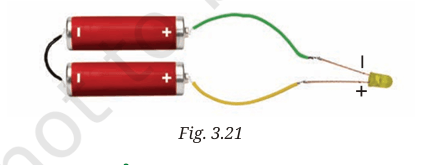
Answer: No, the lamp (LED) will not glow in the given circuit.
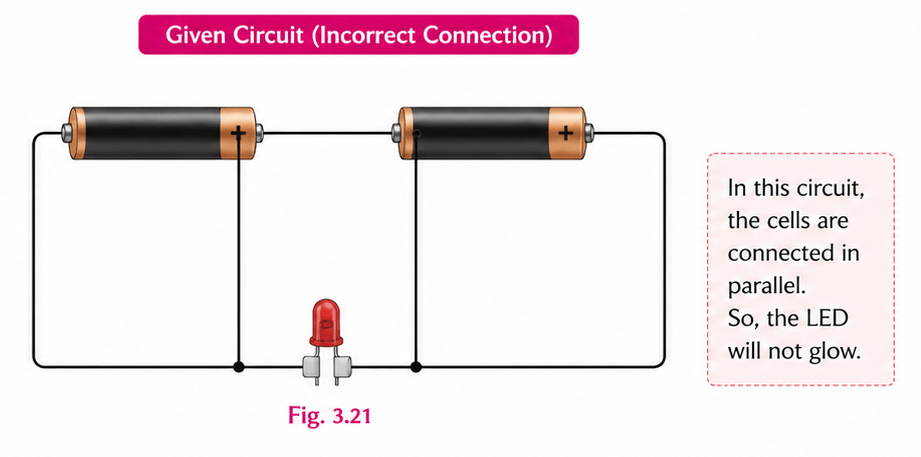
Reason:
– The two cells are not connected in series correctly.
– In a proper series connection, the positive terminal (+) of one cell must be connected to the negative terminal (–) of the other cell.
– Because of an incorrect connection, the required voltage is not supplied to the LED, so it does not glow.
Correct Connection:
To make the LED glow:
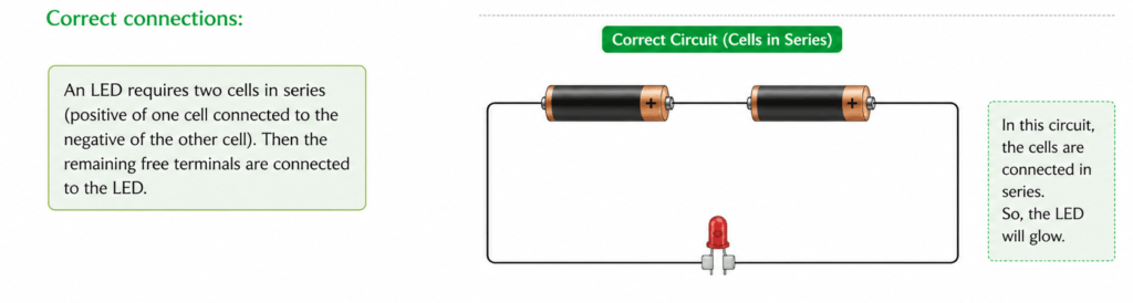
1. Connect the positive (+) terminal of the first cell to the negative (–) terminal of the second cell (series connection).
2. Connect the free negative terminal to one terminal of the LED.
3. Connect the free positive terminal to the other terminal of the LED.
4. Ensure the LED is connected in the correct direction (polarity).
Conclusion:
The LED will glow only when:
– Cells are connected in series properly
– Circuit is closed
– Polarity is correct